

Material Specification |
ROPS Technical Specifications and Information |
|
Brown Davis Automotive uses only the highest grade of materials in the production of every ROPS. The listing below specifies the grading and specification of all components.
|
|
All Brown Davis ROPS kits are designed as bolt in systems to suit individual vehicles. All components are carefully prototyped on a test vehicle to ensure critical tolerances are achieved for a neat fit and optimum protection. Ensuring maximum occupant space is obtained, and entry/exit considerations are maximised, is paramount in each design. Below are some of the key design features of each Brown Davis ROPS unit. |
|
| Footplates/Brackets/Backup Plates: Computerised laser cutting and folding of all foot plates, brackets and back up plates ensures perfect jig and vehicle fitment, allowing Brown Davis to consistently replicate each ROPS with tight tolerances. Folding to stiffen all mounting plates is part of the engineering thoroughness of Brown Davis ROPS designs. | 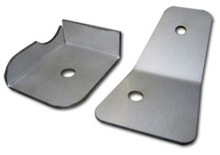 |
| Tube work: As key components to the ROPS structure, the hoops and side bars are a main focus of the production. Each hoop and side bar is bent on the latest CNC mandrel bending machines to produce precise bend angles, and also consistent replication of each ROPS unit. Tooling has been specially produced to ensure the bend radius (145mm centreline for 45.5mm O.D tube) is greater than 3 times that of the tube diameter. Mandrel bending leaves minimal compression of the tube through the bend, and thus maintains the maximum tube section. Both of the above enhance the ROPS assemblies overall structural strength. | 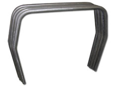 |
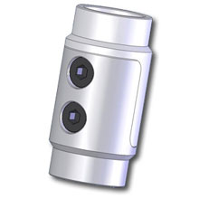
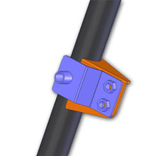
| Brown Davis Rollbar Joiners (patent pending): After years of constant development and testing earlier evolutions, Brown Davis have reached a near perfect solution to the bolt in/kit style assembly, while still satisfying and/or exceeding the tube strength specifications. These joiners have set the bench mark for internal ROPS design. Each item is CNC machined to give consistent assembly of components with tight tolerances. Clever design incorporates recessed bolt heads leaving only a smooth round surface with no protrusions, ensuring there is no risk of injury from upper body contact. This captive thread design also allows tight fitment of the ROPS inside the vehicle cabin to maximise occupant space. Internal steel locating dowels which resist sheer loading, eliminate the possibility of the bolts sheering when forces at 90 degrees are applied to the joiner. Testing of the roll bar joiners has confirmed that they are stronger than the tube itself, in both bending and tensional loads. | 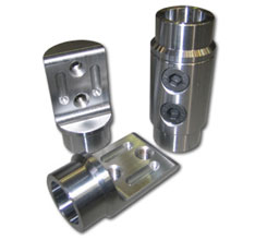 |
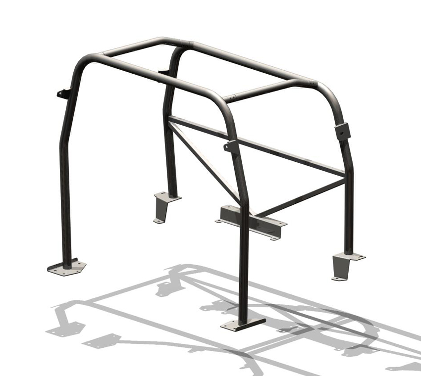
The design of any ROPS needs to take into consideration two very important aspects; Structural mount points and Ergonomics. As each vehicle cabin space can be vastly different, it is important to assess and design a specific solution to each vehicle, rather than a 'generic' design applied to all. Although the visual concept remains similar, each ROPS can vary greatly in size/shape and mounting locations. |
|
|
|
|
|
The use of 3D CAD modelling software has become increasingly beneficial to research and development work in almost all manufacturing industry. Brown Davis takes full advantage of these high tech techniques, to design and model all components prior to any ROPS going to prototype testing or final production. From the footplates, to the rollbar joiners, each component is drafted into a workable 3D model. This in turn gives much greater scope for development and testing any new concepts and ideas. Combined with Finite Element Analysis (FEA), prototypes and testing can be thoroughly scrutinised in great detail. |
|
 |
 |
 |
|
©Brown Davis 2009 - www.browndavis.com.au